- Product description
-
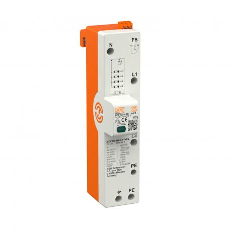
Product descriptionCombination arrester, type 1+2, for mounting on 40 mm busbars, for TN-S and TT systems
• Protection level ≤1.5 kV to protect the terminals
• Lightning protection equipotential bonding according to VDE 0185-305 (IEC 62305)
• Lightning current arresting capacity up to 100 kA (10/350) 3+NPE
• Fulfils the requirements of VDE 0100-534 (IEC 60364-5-53)
• Line follow current quenching up to 50 kA and max. backup fuse up to 315 A gL/gG
• Spark gaps for use in the pre-meter area according to VDE-AR-N 4100
• With potential-free changeover contact for remote signalling
Application: Building with lightning protection or outside cable infeed.
-
- Technical data
-
Technical data
Approvals VDE Arrester surge current (8/20 µs) [total] 100 kA Cable type for surge protection devices Power cable AV Combined voltage protection level [L-PE] 2,5 kV Conductor cross-section, flexible (fine-wire), max. 35 mm² Conductor cross-section, flexible (fine-wire), max. 2 AWG Conductor cross-section, flexible (fine-wire), min. 7 AWG Conductor cross-section, flexible (fine-wire), min. 10 mm² Conductor cross-section, rigid (single-wire/multiwire), max. 35 mm² Conductor cross-section, rigid (single-wire/multiwire), max. 2 AWG Conductor cross-section, rigid (single-wire/multiwire), min. 7 AWG Conductor cross-section, rigid (single-wire/multiwire), min. 10 mm² Connection cross-section, FM terminals, max. 1,5 mm² Connection cross-section, FM terminals, max. 16 AWG Connection cross-section, FM terminals, min. 0,5 mm² Connection cross-section, FM terminals, min. 28 AWG Dimension 255V FM contacts Changeover Follow current quenching capacity (eff) [N-PE] 0,1 kA Height 109 mm Housing material surge protection components PA UL 94 V-0 Installation type Bus bar 40 mm Length 226 mm Lightning surge current (10/350 μs) 25 kA Lightning surge current (10/350) 100 kA Max. mains-side overcurrent protection 315 A Maximum back-up fuse 315 A Maximum continuous voltage (L-N) 255 V Maximum continuous voltage (N-PE) 255 V Maximum continuous voltage AC 255 V Maximum discharge current (8/20 μs) 50 kA Maximum discharge current (8/20 μs) [L-N] 50 kA Maximum discharge current (8/20 μs) [N-PE] 100 kA Network form TN-S, TT Nominal discharge current (8/20 µs) 25 kA Nominal discharge current (8/20 µs) [L-N] 25 kA Nominal discharge current (8/20 µs) [N-PE] 100 kA Nominal voltage AC (50/60 Hz) 230 V Operating temperature, max. 80 °C Operating temperature, min. -40 °C Pole version 3+N/PE Protection level [L-N] ≤1,5 Protection rating IP20 Remote signalling yes Response time <100 ns Short-circuit resistance for max. mains-side overcurrent protection 50 kA eff Signalling on device Visual SPD to EN 61643-11 Type 1+2 SPD to IEC 61643-1 Class I+II Switching power AC 250 V/ 2 A Switching power DC 250 V/ 0,1 A TN network form yes TN-C-S network form yes TN-S network form yes Torque 3,5 Nm TOV voltage [L-N] ‒ fail safe mode ‒ 120 min. 442 V TOV voltage [L-N] ‒ withstand mode ‒ 5 s 440 V TOV voltage [N-PE] ‒ withstand mode ‒ 200 ms 1200 V TT network form yes Version for 3+NPE Width 50 mm - All types
- Downloads
-
Data sheet MCF100-NAR-TT+FS / 5096988 , 0.33MB , pdfCatalogue Überspannungsschutz , 28.42MB , pdfEU declaration of conformity MCF100-NAR-TT+FS / 5096988 , 0.11MB , pdfREACH Declaration of conformity MCF100-NAR-TT+FS / 5096988 , 0.12MB , pdfRoHS Declaration of conformity MCF100-NAR-TT+FS / 5096988 , 0.12MB , pdfLabel approval VDE symbol approval MCF 75, MCF 100 , 0.12MB , pdfLabel approval VDE symbol approval, MCF NAR , 0.12MB , pdfSelection aid Selection aid, surge protection , 2.00MB , pdfMounting instructions Mounting instructions, MCF75-NAR - MCF100-NAR , 0.17MB , pdf


English


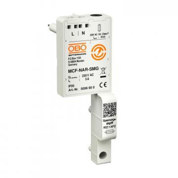
 Voltage tap for MCF-NAR series